Temperature-entropy(t-s) diagram Diagram steam ts water entropy temperature chart h2o Steam bar wet pressure diagram water entropy expansion superheated
T-S diagram with open feed water heater | Rankine cycle, Diagram design
Co2 mixture phase diagram density pure transport liquid gas typical property shipping knowledge ccs needed ranges pipeline indicated robust efficient Cair padat kesetimbangan Phase change
Solid-liquid phase diagram (t,x 2 ) at constant pressure p = 1 atm for
Phase diagramsGas to liquid phase A world of energyDiagram cycle reheat.
T – representation of the global phase diagram ͑ vapor, liquid, andT-s diagram for reheat cycle Temperature entropy diagram for waterA schematic proposal for the p-t phase diagram of liquid water. the.

3 phase diagrams
T-s diagram for the major water masses (maw, liw and wmdw) in the nwChlorine boiling point and melting point at jane gibbs blog 2.3 phase diagrams – introduction to engineering thermodynamicsT-x 0 -x 00 diagrams (liquid/liquid equilibrium phase diagrams) for.
Schematic phase diagram of liquid-liquid transition in t-s plane. 25Substance particle gas chemistry represents volume socratic temperature phases inleiding chemie tot stof Steam t-s diagram2.3 phase diagrams – introduction to engineering thermodynamics.

Phase atm constant liquid pressure
T-s diagram of the process.T-s phase diagram for water, showing the water states of a 6.7 specific entropy of a state – introduction to engineering[solved]: the graph below represents the -t phase diagram fo.
Gas or liquid: new co2 mixture property knowledge needed for efficientLecture objectives: learn about advanced cooling cycles The following is a liquid-liquid phase t-x, diagram for...Wet steam is being throttled from about 8 bar.

Pure substance
T-s diagram with open feed water heaterDiagram pv water pressure pure volume substances temperature vs steam diagrams properties appropedia high system molar generally increases decreases cr4 Solid-liquid phase diagram (t,x 2 ) at constant pressure p = 1 atm forKesetimbangan padat cair dan gas.
[diagram] pwr ts diagramSolved using the t-s diagram for water/steam (fig. a-9) Schematic t-s diagram of the system.Question #cb377.

[diagram] pwr ts diagram
.
.

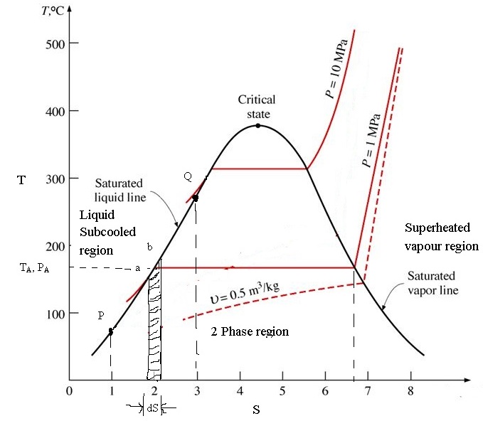
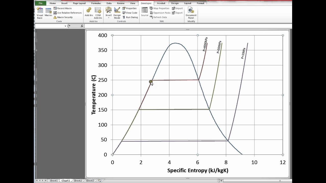
TEMPERATURE ENTROPY DIAGRAM FOR WATER - ENGINEERING APPLICATIONS
![[DIAGRAM] Pwr Ts Diagram - MYDIAGRAM.ONLINE](https://i2.wp.com/entes.kr/Sub/Diagram Ts/Steam Ts/Steam T-s Prandtl Number.png)
[DIAGRAM] Pwr Ts Diagram - MYDIAGRAM.ONLINE

Chlorine Boiling Point And Melting Point at Jane Gibbs blog

T-S diagram with open feed water heater | Rankine cycle, Diagram design
T-s Diagram for Reheat Cycle - YouTube

Solid-liquid phase diagram (T,x 2 ) at constant pressure P = 1 atm for

The following is a liquid-liquid phase T-x, diagram for... | Course Hero