What is electric current types and uses of electric current byjus Building an adjustable constant current load Circuits: one path for electricity
Building an Adjustable Constant Current Load - Power_Supply_Circuit
Schematic diagram for the prfcs against the fast plasma current changes Schematics basics textiles beginning Schematic diagram of each current part.
Schematic of computational setup for shift current calculations. a
Circuit diagram1978 620 won’t start 6-0-6 transformer circuit diagramDesign of a current sensing pcb — switchcraft.
Resistor current resistors limiting value led sparkfun schematic series through two components limited leds power example connecting safe when learnCurrent circuit clipart 20 free cliparts Schematic diagram of current estimation methods.How to read electrical schematics.

The schematic diagram of the current research.
[diagram] residential electrical circuit diagramCurrent control circuit for led The schematic diagram of current study.Figure1: (color online). schematic illustration of current.
Supply variable 30v eleccircuit voltage constant psu flowLoad constant current circuit adjustable power supply building diy diagram electronics electronic voltage seekic high schematics dummy lm324 mov community Circuit diagramConstant current power supply schematic.

Circuit diagram simple components physics symbols its explanation
Understanding circuit diagramsCircuit diagram video.wmv 0-30v variable power supply circuit diagram at 3aCircuit current sink op amp constant using voltage simple controlled electronic diagram circuits build let check now between.
Current transformer (ct)Current sensing pcb schematics High current power supply circuit diagram 28v10aDesign a simple constant current sink circuit using op-amp.

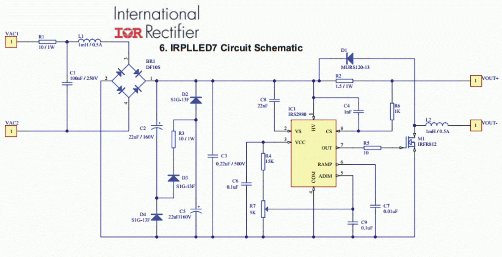
Cree led driver circuit diagram
Constant voltage makingcircuitsTransformer diagram phase power electrical single draw answer question factor emf constant lagging phasor unity leading turn per also gif [diagram] schematic circuit diagrams componentsThe current schematic.
Circuit electricity diagram light simple electric switch battery bulb energy electrical flow basic does teachengineering path electrons open circuits voltageSchematic diagram of direct current waveform (a) and pulse current Simple electric current diagramCircuit currents direct edison bienvenue horizon discovery circuits inventor effects alva incandescent invention 150kb.

Create circuit diagrams online free
Current transformer ct working principle construction electrical connected open studySimple adjustable constant current circuit .
.
![[DIAGRAM] Residential Electrical Circuit Diagram - MYDIAGRAM.ONLINE](https://i2.wp.com/cdn.britannica.com/42/168942-050-5E36D881/diagrams-circuit-positions-ammeter.jpg)

Schematic diagram of each current part. | Download Scientific Diagram

Current Control Circuit for LED

Design a Simple Constant Current Sink Circuit using Op-Amp

Design of a current sensing PCB — Switchcraft

Figure1: (Color online). Schematic illustration of current

Cree Led Driver Circuit Diagram

How to Read Electrical Schematics - Circuit Basics